|
Creative
Power
Resources, Inc. 226 Palmer Road Bangor, PA 18013 
CPR: Bringing Powerful Ideas To Life! Robert L Rauck Ph: 215-362-0258 Fax: 215-362-3458 For Analog, Power Electronics or Motion/Process Control Consulting Support, E-Mail: ee@consult-cpr.com |
||||||
|
Technical Article & File Download
|
||||||
|
Converter Flux-Walking
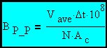
by Robert L Rauck Managing the operating flux density of the transformer in a transformer-coupled Switch Mode Power Converter is always an important consideration in overall converter design. Such converters can be broadly divided into two categories: unipolar and bipolar transformer drive types. Each converter type has it's unique set of considerations. There is a subset of the bipolar drive converter type that have an important complication factor that is the subject of this article. This subset is voltage-fed (rather than current-fed) and has the drive voltage DC coupled to the transformer primary (no coupling capacitor) and does not use current-mode control. Examples of this type of converter include push-pull and bridge circuits. These converters are subject to a phenomena known as flux-walking. Let's examine the expression for flux density in a transformer core:
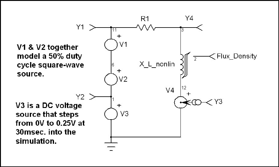
This expression (CGS Units) is developed in the companion article on magnetic flux density and will not be repeated here. Examination of the above expression reveals that core flux is a function of the applied volt-seconds and the physical characteristics of the magnetic design. The volt-seconds in question are applied during a single half-cycle of the input waveform. The following simple example (see schematic) uses a 50% duty cycle square-wave drive to the transformer. The resulting flux in the core will have a triangular wave-shape. This circuit includes a saturating model for the transformer core that will properly reflect the actual core flux due to the applied voltage waveform. The model will be run for two applied voltage cases: with no DC voltage component and with a DC component. We will see graphically the effect of applying a drive waveform that does not have perfect balance in the volt-second content of the two half-cycles of the input waveform. Obviously, Volt-second unbalance can occur when either the half-cycle voltages or half-cycle times are unbalanced. For convenience, we will unbalance the half-cycle voltages by turning on a 0.25VDC source in series with the applied drive voltage 30 msec. into the simulation. The term Vave•Δt (volt-seconds) in the above expression determines the flux excursion for a given magnetic design. I have seen many engineers fall into the trap of trying to solve a flux-walking problem by designing the transformer to operate at a low flux density to allow reserve for unbalance. This will not work because the equation predicts that the problem will be cumulative over many cycles when the excursions on positive and negative half-cycles are not equal. This behavior has led to the name, flux-walking. Consider the following simulation schematic:
For simplicity, only the transformer primary winding is shown.
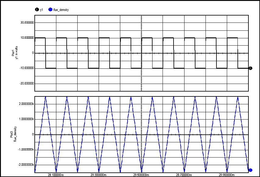
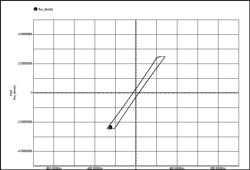
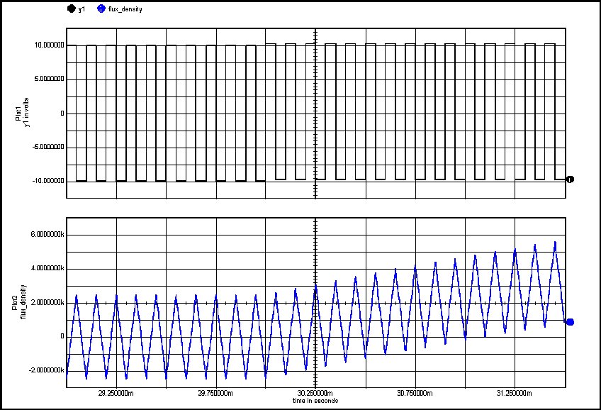
The top waveform is the applied voltage and the bottom waveform is the resulting core flux (in gauss) for a hypothetical core I have modeled. The following plot shows the B-H loop (vertical axis is B & horizontal axis is current which is proportional to H). We can see that, in this case, we have volt-second balance and the core does not walk.
Next we extend the analysis beyond the point the DC offset is introduced (30 msec. into simulation) and observe the result.
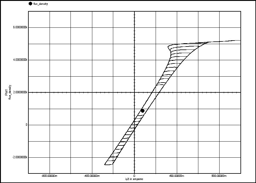
We can see that, in this case, we do not have volt-second balance and the core walks. The corresponding B-H loop will clearly illustrate flux-walking and the onset of core saturation:
The transformer can clearly be seen walking to saturation. The result (without limiting) is an explosion in the converter power stage. Not good!! There are a number of ways the unbalance can arise ranging from unequal switch voltage drops to noise in the control loop at one-half the PWM ramp frequency (leading to unbalanced half-cycle times). This loop noise is one type in the general class of synchronous noise (harmonically related to the switching frequency) in the control loop that have various negative effects on converter performance. This general topic will be the subject of a future article. Unbalanced drive volt-seconds causes the flux walking and therefore any resistance in series with the transformer primary helps to limit this process. The I•R voltage drop will be unbalanced in the opposite direction to that of the drive source. This effect can be helped further by putting a gap in the transformer core to lay the loop over and increase the I•R drop at a given gauss level. Remember, the core will continue walking until the applied volt-seconds (downstream of any I•R drop) is balanced. Peak current-mode control has the potential to fix the problem if the current sensor is monitoring transformer primary current and can detect a DC component in the current signal. Certain current sense transformer configurations cannot see the DC component but resistive sensors always work. Current-fed converters normally do not suffer from this problem since the feed inductor serves to filter transformer primary current and therefore it will develop a correction voltage to balance the two half-cycles. |
||||||
| Download PDF Copy of Article Converter Flux-Walking.pdf |