|
Creative
Power
Resources, Inc. 226 Palmer Road Bangor, PA 18013 
CPR: Bringing Powerful Ideas To Life! Robert L Rauck Ph: 215-362-0258 Fax: 215-362-3458 For Analog, Power Electronics or Motion/Process Control Consulting Support, E-Mail: ee@consult-cpr.com |
||||||||||||||||||||||||||||||
|
Technical Article & File Download
|
||||||||||||||||||||||||||||||
|
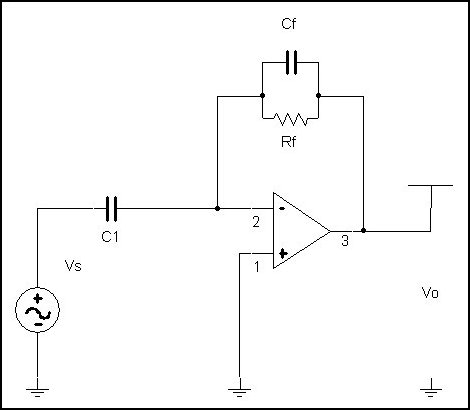
Amplifier AC Design Problem
by Robert L Rauck Here is the analysis of an amplifier that shows the development of the gain expressions for an inverting amplifier and illustrates the origin of the difficulty in getting the amplifier to work as desired. This hypothetical amplifier was intended to be a high pass filter with the gain breaking flat (+60dB) at ~ 160 Hz and the maximum frequency of interest being 5kHz. The amplifier does not work as intended and this analysis will show why. This analysis is somewhat simplified in that it ignores Op Amp bias and offset currents and offset voltage since DC performance was not the object of the analysis. Real Op Amps also exhibit additional break frequencies not modeled here (usually near open loop gain cross-over) but again these were irrelevant to this analysis. Parasitic reactances associated with the layout of PC Boards can also affect the high frequency performance of real amplifiers. Rf = 50.103 C1 = 20.10-6 G0 = 1.105 Cf = 0.02.10-6
>
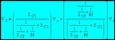
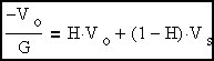
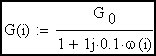
By definition: VO = -V2.G where G is the open loop gain of the amplifier
i = 0,0.1..4 f(i) = 10i Here we set up a range variable that allows us to sweep frequency.
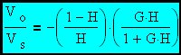
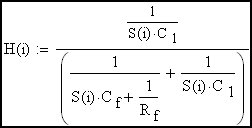
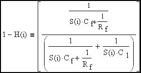
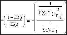
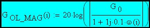
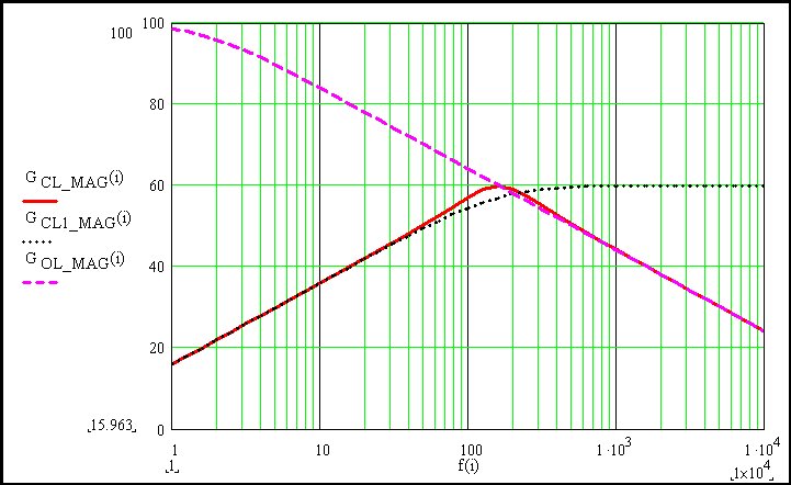
Now we will assemble expressions for the magnitudes (dB) of actual of amplifier closed loop gain (GCL_MAG(i)), ideal amplifier closed loop gain (GCL1_MAG(i)) assuming a perfect Op Amp and the open loop gain (GOL_MAG(i)) of the chosen Op Amp. We will plot the results.
Here we can see the interplay of amplifier open loop gain (GOL_MAG(i)) and ideal closed loop gain (GCL1_MAG(i)) resulting in actual closed loop gain (GCL_MAG(i)). The amplifier runs out of gain and fails to follow the ideal gain expression above ~ 100Hz. |
||||||||||||||||||||||||||||||
| Download PDF Copy of Article Amplifier AC Design Problem.pdf |