|
Creative
Power
Resources, Inc. 226 Palmer Road Bangor, PA 18013 
CPR: Bringing Powerful Ideas To Life! Robert L Rauck Ph: 215-362-0258 Fax: 215-362-3458 For Analog, Power Electronics or Motion/Process Control Consulting Support, E-Mail: ee@consult-cpr.com |
||||||||
|
Technical Article & File Download
|
||||||||
|
Amplifier External Noise Analysis
by Robert L Rauck
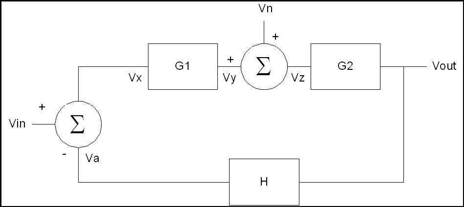
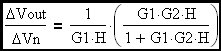
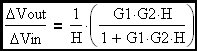
It is often necessary to evaluate the effect of external noise sources on an amplifier's performance. It turns out that an amplifier's sensitivity to noise depends on a number of factors, not the least of which is where the noise enters the signal path. The above diagram illustrates a noise voltage (Vn) entering the loop at a point within the forward signal path of the amplifier. The question naturally arises as to the noise amplitude at the circuit output. The following analysis will develop expressions to answer that question. Va = H•Vout Vx = Vin - Va Vy = G1•Vx Vz = Vin + Vy Vout = G2•Vz Therefore: Vout = G2•[Vn + G1•(Vin - H•Vout)] Substituting from all the above expressions Vout = G2•Vn + G1•G2•Vin - G1•G2•H•Vout Completing the indicated multiplications
Now the actual input signal times its' gain determines its' amplitude at the circuit output and the same applies to the noise signal. The ratio of these output signal component amplitudes will give the signal to noise ratio at the output. It must be remembered that the relative magnitudes of the various frequency components of the input signal (and of the noise signal) and their respective gain vs frequency functions (defined above) will need to be included in this analysis. The result is a signal to noise ratio that is a function of frequency. Further analysis of the highlighted equation above reveals that signal to noise ratio is improved (for a given total forward path gain: G1•G2) by moving as much gain as possible to the G1 block that precedes the noise entry point. It must be pointed out that the amplifier is a source of noise all by itself. Low noise applications, especially, must carefully consider internally generated noise but that is a seperate analysis topic. |
||||||||
| Download PDF Copy of Article Amplifier External Noise Analysis.pdf |