|
Creative
Power
Resources, Inc. 226 Palmer Road Bangor, PA 18013 
CPR: Bringing Powerful Ideas To Life! Robert L Rauck Ph: 215-362-0258 Fax: 215-362-3458 For Analog, Power Electronics or Motion/Process Control Consulting Support, E-Mail: ee@consult-cpr.com |
|||||||||||||||||||||||||||||||||||||||||||||||
|
Technical Article & File Download
|
|||||||||||||||||||||||||||||||||||||||||||||||
|
First Order System Rise Time
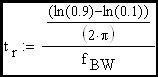
by Robert L Rauck Analog designers are often called upon to design an amplifier to meet a specific rise time requirement. Amplifiers with feedback loops that exhibits a first order roll-off are the easiest to characterize. One of the rules of thumb often used in such cases is the following equation:
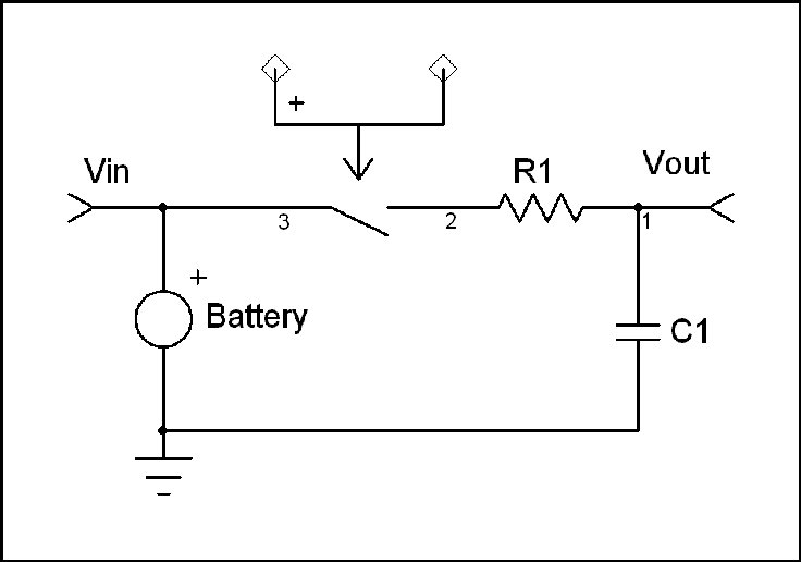
This expression is used all the time but many engineers do not know where it came from or how to derive it. The origin of this expression arises from the behavior of a R-C network when excited by a step input.
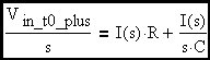
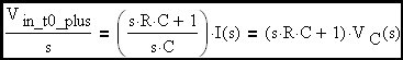
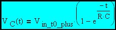
Let's write an expression for the behavior of this circuit at switch closure using Laplace Transform notation. The circuit input is a step function due to the presence of the switch. We will assume the capacitor is initially uncharged.
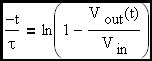
Now let's take the inverse transform.
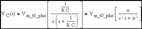
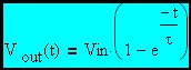
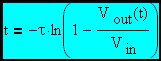
From here forward we will refer to the input voltage as Vin since it is a constant. In this circuit, the capacitor voltage is the output voltage. Therefore:
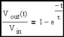
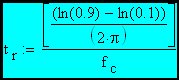
Here a specific corner frequency has been picked to stimulate the discussion.
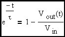
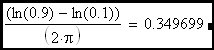
Clearly the rise time of an R-C circuit can be expressed as approximately 2.2•τ which, as we can see, is equal to approximately 0.35 devided by the R-C corner frequency (fc). Now we would like to extend this discussion to include the feedback amplifier case where the R-C corner frequency is replaced in the expression by the loop cross-over frequency.
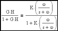
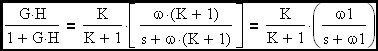
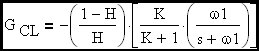
Assume that G is a gain block with an embedded R-C filter to give it a first order roll-off at a frequency more than one decade below loop cross-over. Let's examine this expression at loop cross-over where G•H = 1 at an angle of -90 degrees since we are more than a decade beyond the R-C corner embedded in G. The term G•H/(1+G•H) is an error term that determines the departure of closed loop gain from the ideal gain term (flat with frequency) defined above.
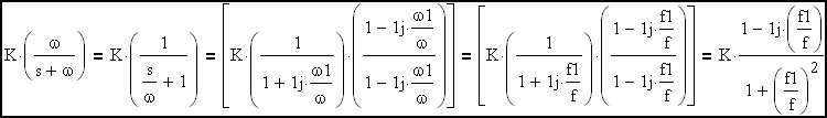
Let's focus on when the magnitude of G*H is 1 (loop cross-over frequency):
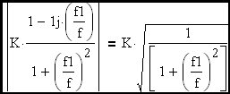
The loop cross-over frequency will converge to K•f; (where f is the R-C corner freq. of the embedded R-C filter) when K is >> 1. The corner frequency of the closed loop transfer function represented by this amplifier circuit will be shown to be (K+1)•f which is ~ K•f when K is >> 1. Therefore we have demonstrated that the amplifier will behave like a simple R-C circuit (multiplied by a constant to account for amplifier DC gain) where the effective corner frequency is essentially the loop cross-over frequency.
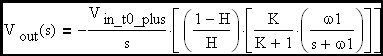
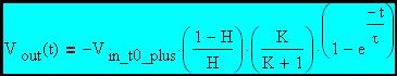
The complete transfer function is therefore:
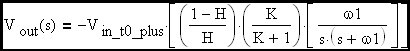
Now let's take the inverse transform:
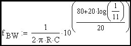
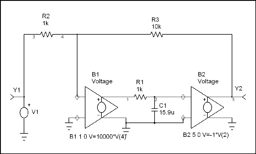
This expression has the same form as the transfer function of the simple R-C circuit defined above (except for the DC gain term ((1-H) / H)•(K/(K+1)). Therefore the rise time of the amplifier will have the same form as the R-C circuit. Stated another way, the loop cross-over frequency is the effective corner frequency of the amplifier closed loop transfer function. One equivalent circuit would be a frequency independant gain block in series with an equivalent R-C circuit. In this case the effective R-C corner frequency would be shifted to the loop cross-over frequency. The important thing to remember is that G•H / (1 + G•H) of a first order roll-off loop looks like the frequency response of a simple R-C network when the ideal closed loop gain is flat with frequency. In the schematic that follows, I have modeled an amplifier that has the characteristics we have discussed. Here B1, B2 and the R-C network are used to model an Op Amp that has an open loop gain of -10,000 and a gain roll-off at 10 Hz. B1 and B2 are user definable gain blocks that I have defined as indicated on the schematic. If we examine the closed loop gain of this amplifier, we see that it is flat at -10 until cross-over where it begins to roll off. The DC loop gain is G•H = 80dB + 20•log(R2/(R2+R3)) = 59.172dB and therefore the ratio of corner freq to cross-over freq is 1059.172/20 = 909.076 times the 10 Hz corner frequency of R1•C1 or 9.09 kHz cross-over freq.
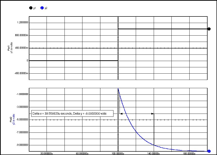
Now we will simulate the above circuit and compare the rise time result with the predicted performance.
Success! Simulation matches prediction. |
|||||||||||||||||||||||||||||||||||||||||||||||
| Download PDF Copy of Article First Order System Rise Time Rev A.pdf |